TENGHUI provides sheet metal welding services for custom brackets, panels, frames, chassis, enclosures, cabinets, and other fabricated assemblies. Available processes include laser welding, TIG welding, MIG welding, and resistance spot welding.
The welding method is selected according to your material, thickness, joint design, strength requirements, production quantity, and desired appearance. Controlled fit-up, suitable fixtures, and planned welding sequences help reduce distortion and maintain important assembly dimensions.
✅ All Design Uploads Are Secure & Confidential
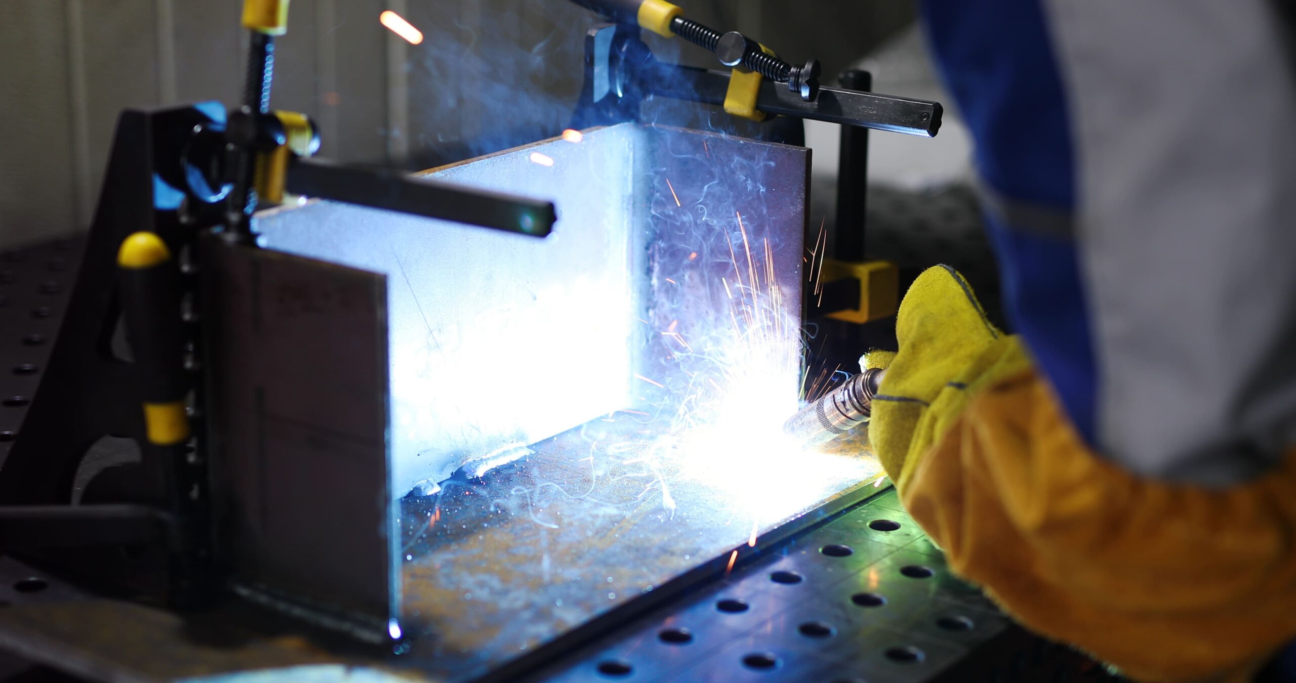
Laser welding creates narrow, consistent weld seams with concentrated heat input. It is suitable for thin sheet metal, long seams, visible joints, and repeat production where reduced distortion and clean appearance are important.
TIG welding provides precise control over heat input and filler material. It is commonly used for stainless steel, aluminum, thin sheets, prototypes, complex joints, and cosmetic welds.
MIG welding provides faster welding speeds and efficient filler-metal deposition. It is suitable for carbon steel, stainless steel, aluminum frames, brackets, structural parts, and larger assemblies.
Spot welding joins overlapping sheet metal parts quickly and consistently. Typical applications include panels, cabinets, chassis, covers, brackets, and repeat production assemblies.
Not every material or thickness is suitable for every welding method. Final feasibility and process optimization are confirmed after reviewing your technical drawings and material specifications.
| Material | Available Grades | Welding Considerations |
|---|---|---|
| Carbon Steel | SPCC, SPHC, DC01, DC05, Q235, Q355 | Commonly used for brackets, frames, panels, and structural assemblies. |
| Stainless Steel | SUS301, SUS304, SUS316 | Requires controlled heat input to limit thermal distortion and heat discoloration. |
| Aluminum | 5052, 5754, 5083, 6061 | Requires suitable filler material, rigorous surface preparation, and proper shielding gas. |
| Galvanized Steel | SECC, SGCC | Requires engineering review because the zinc coating affects welding conditions and appearance. |
| Copper, Brass & Titanium | Selected projects | Feasibility depends on material grade, thickness, joint design, and welding process. |
Welded brackets, reinforcement braces, and heavy-duty structural frames designed to provide reliable load-bearing support and mechanical stability.
Precision-welded electronic chassis and multi-side enclosure bodies built to house internal components securely while maintaining tight tolerances.
Robust electrical cabinets and automation control boxes featuring clean, sealed weld seams designed to protect sensitive electrical components.
Custom equipment faceplates, exterior side panels, and protective covers fabricated with smooth, high-cosmetic weld finishes for industrial devices.
Safety machinery guards and reinforced mounting trays built to withstand rigorous industrial operational environments and secure moving parts.
Specialized stainless steel and aluminum enclosures engineered for corrosion resistance, cleanroom compliance, and lightweight structural performance.
Welding introduces localized heat, shrinkage, and residual stress. Final assembly accuracy depends on the material, thickness, joint design, weld length, fixture, and overall geometry. TENGHUI controls weld quality through rigorous engineering steps.
Material specifications, weld symbols, joint locations, assembly tolerances, and appearance requirements are carefully reviewed before production.
Joint gaps, component alignment, welding access, and critical dimensions are thoroughly checked before welding begins.
Welding power, current, speed, shielding gas, filler material, and weld sequence are selected according to the specific process and material.
The first welded assembly is inspected for weld appearance, dimensional stability, alignment, and assembly fit before repeat production.
Accessible weld surfaces are visually checked for continuity, size, undercut, porosity, spatter, and burn-through. Critical dimensions, flatness, squareness, and hole positions are inspected according to drawings.
A single standard tolerance cannot be applied to every welded assembly because welding heat and shrinkage affect different structures in different ways. Identify critical dimensions and inspection datums on 2D drawings so achievable tolerances can be confirmed before production.
Base material properties and sheet or plate thickness directly influence heat distribution and structural shrinkage during the welding process.
Overall structural dimensions, profile complexity, and spatial geometry dictate how cumulative thermal distortion develops.
The specific type of weld, total seam length, and spatial placement determine the concentration and symmetry of residual stresses.
Choosing between continuous sealing welds and intermittent stitch welding directly affects heat input and total structural shrinkage.
Proper welding fixture design and clear inspection datum selection restrain movement and maintain relative component alignment.
Strict geometrical tolerances for flatness, parallelism, and squareness require specialized clamping and controlled welding sequences.
Post-weld mechanical grinding, flush finishing, or cosmetic blending can alter local dimensions and should be factored into overall tolerances.
For an accurate quotation and seamless manufacturing, please provide a 3D CAD model alongside a fully dimensioned 2D drawing covering all critical welding requirements and specifications.
Specify the precise base alloy grade and exact sheet or plate thickness required for the welded assembly.
Clearly indicate the specific welding method, seam dimensions, total length, and exact spatial placement.
Define whether the joints require continuous full-seam sealing or structured intermittent stitch welding.
Include standard engineering weld symbols, notation conventions, or regional fabrication standards where applicable.
Identify primary inspection datums and critical assembly dimensions to ensure structural alignment and fit-up.
State strict geometrical tolerances for overall component flatness, parallelism, and right-angle squareness.
Highlight exterior visible surfaces that require specialized cosmetic finishes or low-distortion attention.
Specify post-weld mechanical requirements, such as flush grinding, smooth blending, or corner dressing.
Detail any special quality checks, pressure testing, or non-destructive evaluation protocols needed for the project acceptance.
Available processes include laser welding, TIG welding, MIG welding, and resistance spot welding.
Laser welding is suitable for narrow seams and reduced heat input. TIG provides precise control and clean appearance. MIG is efficient for longer welds and larger assemblies. Spot welding is suitable for overlapping thin sheets. The final process is selected after drawing review.
Carbon steel, stainless steel, and aluminum are commonly welded. Galvanized steel, copper, brass, and titanium projects require engineering review.
Accurate fit-up, suitable fixtures, controlled heat input, tack welding, and planned welding sequences help reduce warping and shrinkage.
Yes. Weld grinding and cosmetic blending are available when specified. Visible surfaces and the required final appearance should be identified on the drawing.
Provide a STEP or STP model together with a dimensioned PDF, DXF, or DWG drawing. Include the material, thickness, weld symbols, joint locations, tolerances, quantity, and appearance requirements.
Provide a STEP or STP model together with a dimensioned PDF, DXF, or DWG drawing. Include the material, thickness, weld symbols, joint locations, tolerances, quantity, and appearance requirements.
Once we receive your design files, our senior manufacturing engineers will manually perform a comprehensive DFM review and deliver an accurate, optimized quote within 24 hours.