TENGHUI provides simultaneous 5-axis and 3+2 CNC machining services for custom parts with complex contours, angled features, deep cavities, and features located on multiple sides. Our five-axis capabilities reduce the number of setups, improve tool access, and maintain feature-to-feature consistency from prototypes to production runs.
We primarily machine aluminum components and also support stainless steel, other metals, engineering plastics, and selected advanced materials. Standard machining tolerances are typically ±0.05 mm, with tolerances down to ±0.01 mm available for selected critical features.
Quotes are typically provided within 24 hours after complete drawings and project requirements are received.
Your CAD files and technical information are handled securely and confidentially.
✅ All Design Uploads Are Secure & Confidential
Five-axis CNC machining allows a cutting tool to move along three linear axes—X, Y, and Z—while two additional rotary axes change the orientation of the cutting tool or workpiece.
This additional movement allows the cutting tool to approach a component from multiple angles, making five-axis machining suitable for complex contours, angled holes, deep cavities, compound surfaces, and features positioned on several sides of a part.
The exact rotary-axis configuration varies by machine design. Our engineering team selects the appropriate machine, workholding method, and machining strategy according to the part geometry, tolerances, material, and quantity.
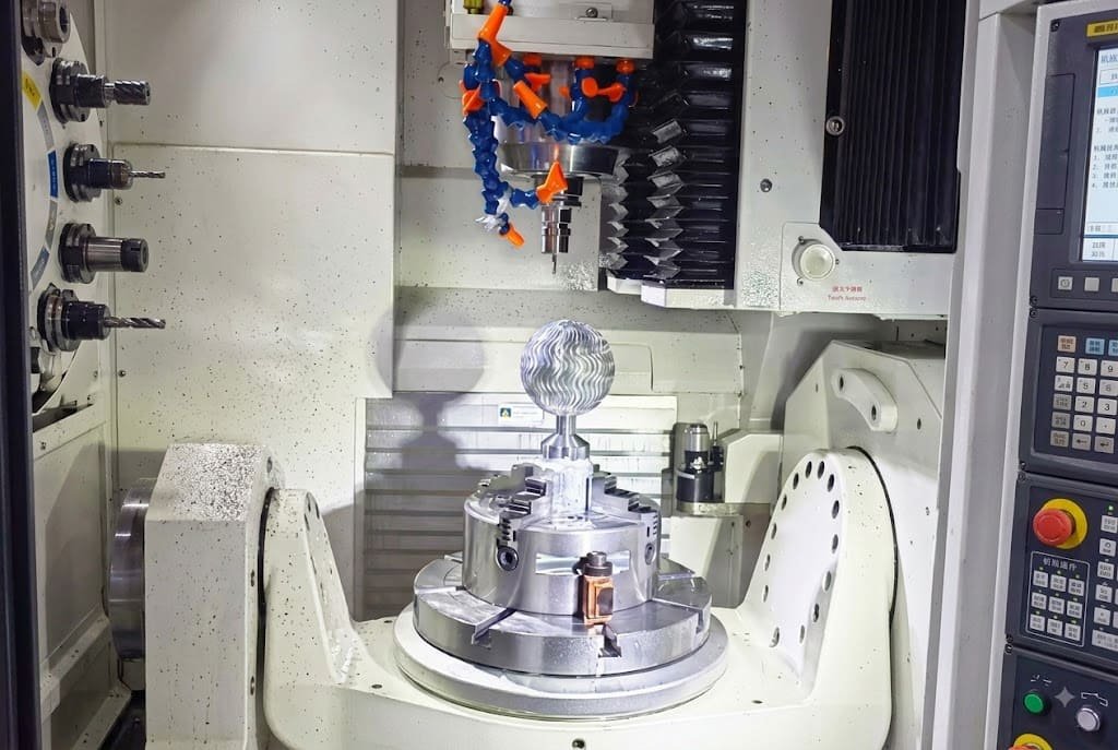
Both methods use five-axis equipment, but they differ in how the rotary axes move during cutting.
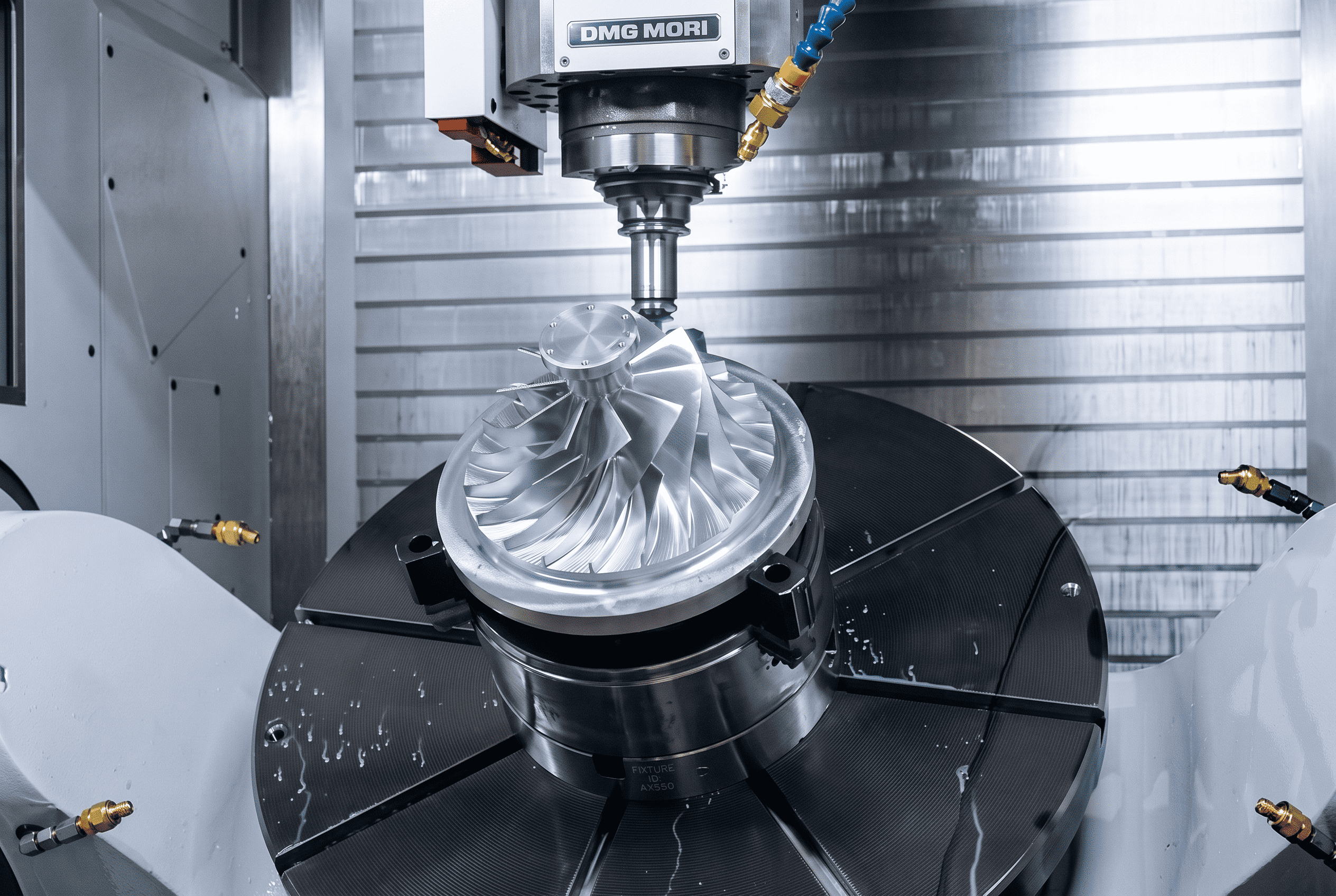
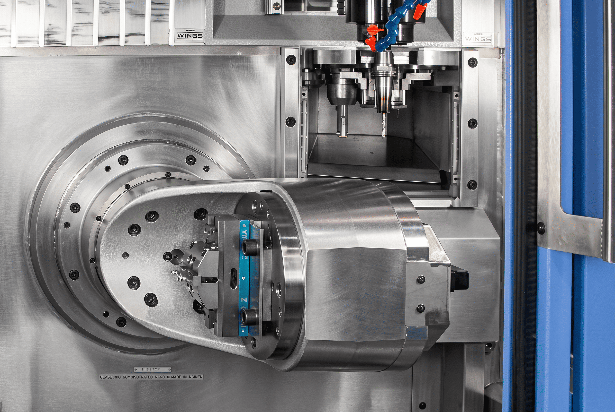
Our five-axis machining capabilities support complex metal and plastic parts from prototypes to repeat production. Each project is reviewed according to its geometry, material, tolerances, workholding requirements, tool access, and inspection plan.
Capability | Specification | Important Considerations |
Machining Methods | Simultaneous 5-axis and 3+2 machining | The most suitable method depends on part geometry, surface requirements, tolerance, and production cost. |
Maximum Part Footprint | Up to 650 × 450 mm | Maximum part height and weight depend on the machine configuration, workholding, tool access, and required rotary movement. |
Standard Machining Tolerance | Typically ±0.05 mm | Suitable for general dimensions and non-critical features. |
Precision Machining Tolerance | Down to ±0.01 mm | Available for selected critical features after engineering review. |
Production Quantities | Prototypes to repeat production | Lead time and capacity depend on part complexity, material, machining time, and inspection requirements. |
Primary Materials | Aluminum alloys and stainless steel | Other materials are available after a project-specific review. |
Please submit your 3D CAD model and fully dimensioned 2D drawing so our engineering team can confirm machining capacity, feature accessibility, tolerances, workholding, and inspection requirements.
Five-axis machining allows multiple sides and angled features to be accessed in fewer setups. This can reduce manual repositioning, fixture changes, and accumulated setup variation.
The additional rotary axes provide access to angled faces, compound contours, deep cavities, and features that may be difficult or inefficient to reach with conventional three-axis machining.
Machining multiple features in one controlled setup can improve the positional relationship between holes, surfaces, and other critical features.
Tilting the tool or workpiece can provide a more suitable cutting orientation, allowing the use of shorter and more rigid tools for selected deep or angled features.
Continuous control of the tool orientation can help produce smoother transitions across complex contoured surfaces and may reduce the need for manual finishing.
For suitable components, consolidating several operations into one machining process can reduce total setup time and simplify production planning.
Five-axis machining is not necessary for every component. Compared with conventional three-axis machining, it may require more advanced CAM programming, machine simulation, workholding, and process verification.
Five-axis machining tolerances define the allowable variation between dimensions specified on a 2D technical drawing and the measured dimensions of the finished part.
Tighter tolerances may require controlled workholding, additional tool passes, temperature management, process verification, and more extensive inspection. Five-axis capability improves access and reduces setups, but achievable accuracy still depends on the complete manufacturing process.
Tolerance Category | Metric Capability | Imperial Capability | Typical Applications |
Standard Machining Tolerance | Typically ±0.05 mm | Typically ±0.002 in | General dimensions, contours, pockets, holes, and non-critical features |
Precision Machining Tolerance | Down to ±0.01 mm | Down to ±0.0004 in | Selected critical features, locating surfaces, precision holes, mating interfaces, and assembly features |
Geometric Tolerances | Drawing-dependent | Drawing-dependent | Position, profile, flatness, perpendicularity, parallelism, concentricity, and runout |
Use these general recommendations to improve manufacturability, reduce unnecessary machining time, and control production costs. These values are recommended starting points rather than fixed manufacturing limits.
Design Feature | Recommended Guideline | Practical Considerations |
Maximum Part Footprint | Up to 650 × 450 mm | Maximum height and weight require review because the part and fixture need clearance during rotary movement. |
Minimum Wall Thickness | Metals: ≥0.8 mm; plastics: ≥1.5 mm | Thin walls may vibrate, deflect, or deform during machining. Taller walls and softer materials may require greater thickness. |
Deep Pockets | Keep the depth-to-width ratio at approximately 4:1 or less where possible | Deep, narrow pockets may require longer tools and increase vibration, tool deflection, and machining time. |
Internal Corner Radii | Minimum radius ≥1.0 mm; larger radii preferred for deeper cavities | Larger corner radii allow stronger tools to be used and improve machining efficiency and surface quality. |
Hole Depth | Preferably ≤5× the hole diameter | Deeper holes may require extended tooling, staged drilling, or specialized processes. |
Angled Features | Clearly define all angles and reference datums on the 2D drawing | Complete dimensions and datum references help engineers select the correct machining orientation and inspection method. |
Undercuts | Avoid where possible or use standard dimensions | Tool access must be evaluated even on five-axis equipment. Some undercuts may still require specialized tools or EDM. |
Dimensional Tolerances | Standard: ±0.05 mm; down to ±0.01 mm for selected critical features | Apply tight tolerances only where they are functionally necessary. |
Surface Roughness | Typical as-machined finish: approximately Ra 1.6–3.2 μm | Finer finishes may require additional tool passes, polishing, grinding, or other secondary operations. |
Datum Strategy | Use clear, functional datums | A practical datum system supports machining, workholding, dimensional inspection, and assembly requirements. |
Cosmetic Surfaces | Clearly identify critical cosmetic surfaces | Surface direction, tool marks, blending requirements, and post-processing should be specified before production. |
Please submit your 3D CAD model and fully dimensioned 2D drawing for a project-specific DFM and machining feasibility review.
Our five-axis machining work primarily involves aluminum components. We also machine stainless steel, engineering plastics, composites, and selected advanced materials according to project requirements.
We coordinate secondary processes to improve the appearance, corrosion resistance, wear resistance, and functional performance of five-axis-machined parts.
Complex five-axis parts often involve multiple datums, compound surfaces, angled features, thin walls, and tight positional relationships. TENGHUI manages these critical requirements through engineering review, process planning, stable workholding, toolpath verification, in-process checks, and final dimensional inspection.
Five-axis machining is ideal for high-precision, complex components across critical industrial sectors. All parts are manufactured to customer specifications.
Five-axis machining is suitable when a part contains complex contours, angled holes, deep cavities, compound surfaces, or critical features located on multiple sides. It can reduce the number of setups and improve access to features that would otherwise require several fixtures or machining operations.
Not every component requires five-axis machining. Simpler parts may be produced more economically using three-axis or four-axis equipment.
The main cost factors include material, part geometry, programming time, machining time, workholding, number of tools, tolerances, surface finish, quantity, and inspection requirements.
Costs can often be controlled by:
Applying tight tolerances only to critical features
Increasing internal corner radii
Avoiding unnecessarily deep or narrow cavities
Simplifying non-functional surfaces
Using standard holes and threads
Selecting readily available materials and stock sizes
Defining practical datums
Limiting special finishes to required surfaces
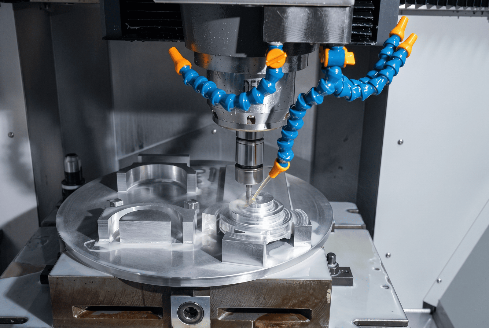
Five-axis machining does not eliminate cutting forces. Thin walls and delicate features still require suitable material preparation, stable workholding, controlled cutting parameters, appropriate machining sequences, and careful inspection.
Improved tool orientation may allow shorter tools and better access, helping reduce vibration and deflection for suitable features.
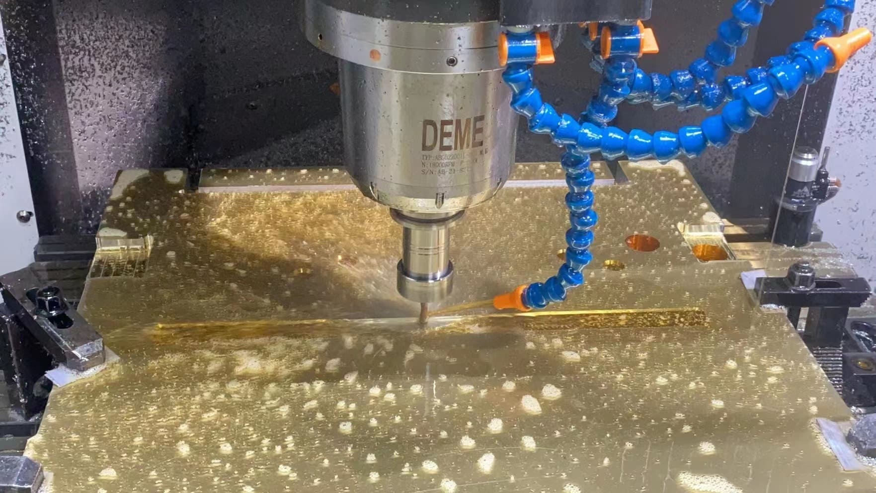
TENGHUI combines simultaneous five-axis and 3+2 machining with direct engineering support, dimensional inspection, and coordinated secondary processing. Our team supports projects from prototypes and low-volume runs to repeat production.
Our standard machining tolerance is typically ±0.05 mm, with tolerances down to ±0.01 mm available for selected critical features after engineering review.
Simultaneous five-axis machining is appropriate for continuous contours, compound curves, and features requiring the tool orientation to change during cutting. In 3+2 machining, the rotary axes position the part at a fixed angle before three-axis cutting begins.
For multi-sided prismatic parts, 3+2 machining may provide the required access at a lower programming and machining cost.
Our five-axis machining centers accommodate parts with a maximum footprint of up to 650 × 450 mm. Maximum height and allowable workpiece weight depend on the machine configuration, geometry, workholding, tool access, and required rotary movement.
Please submit your 3D CAD model and 2D drawing for confirmation.
Our standard machining tolerance is typically ±0.05 mm. Tolerances down to ±0.01 mm can be achieved for selected critical features after engineering review.
Achievable tolerances depend on the material, part size, geometry, wall thickness, workholding, surface finish, and inspection requirements.
No. The number of machine axes does not determine accuracy by itself. Accuracy depends on the machine condition, programming, tooling, workholding, material, thermal stability, machining strategy, and inspection method.
The primary advantages of five-axis machining are improved tool access, fewer setups, and more efficient production of complex geometries.
Yes. As a general guideline, we recommend minimum wall thicknesses of 0.8 mm for metals and 1.5 mm for engineering plastics.
Thinner walls may be possible after engineering review, but they may require specialized workholding, staged machining, controlled cutting parameters, and additional inspection.
Five-axis machining improves access to many angled features, undercuts, and deep cavities, but it does not make every feature machinable. Tool diameter, tool length, holder clearance, workholding, and collision risk must still be evaluated.
Some inaccessible features may require specialized cutters, EDM, or a design change.
Use practical tolerances, larger internal radii, accessible features, standard holes and threads, and readily available materials. Clearly defined datums and limiting special finishes to functional surfaces can also reduce programming, machining, and inspection time.
Our engineering team can provide DFM recommendations after reviewing your drawings.
Please provide a 3D CAD model, fully dimensioned 2D drawing, material grade, quantity, tolerances, surface finish, inspection requirements, and target delivery date. STEP or STP files and PDF drawings are preferred.
Yes. Material certificates, dimensional inspection reports, CMM reports, and surface-treatment certificates can be provided upon request. Documentation requirements should be specified before ordering.
Lead time depends on the material, part complexity, programming, machining time, quantity, workholding, secondary processes, and inspection requirements. A project-specific production schedule will be provided after engineering review.
Once we receive your design files, our senior manufacturing engineers will manually perform a comprehensive DFM review and deliver an accurate, optimized quote within 24 hours.