Certified Industrial Welding Fleet

Custom Sheet Metal Welding Services

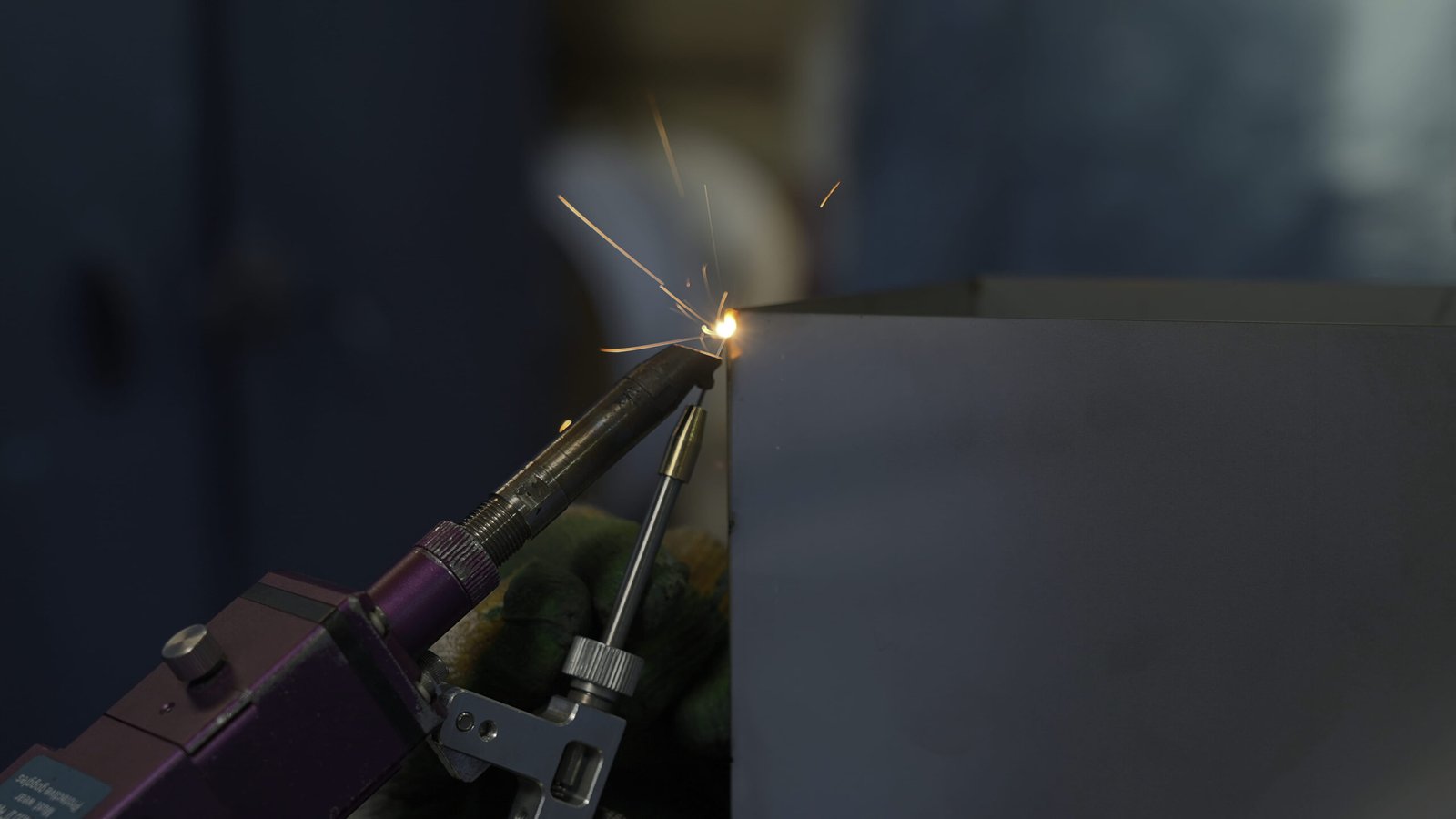
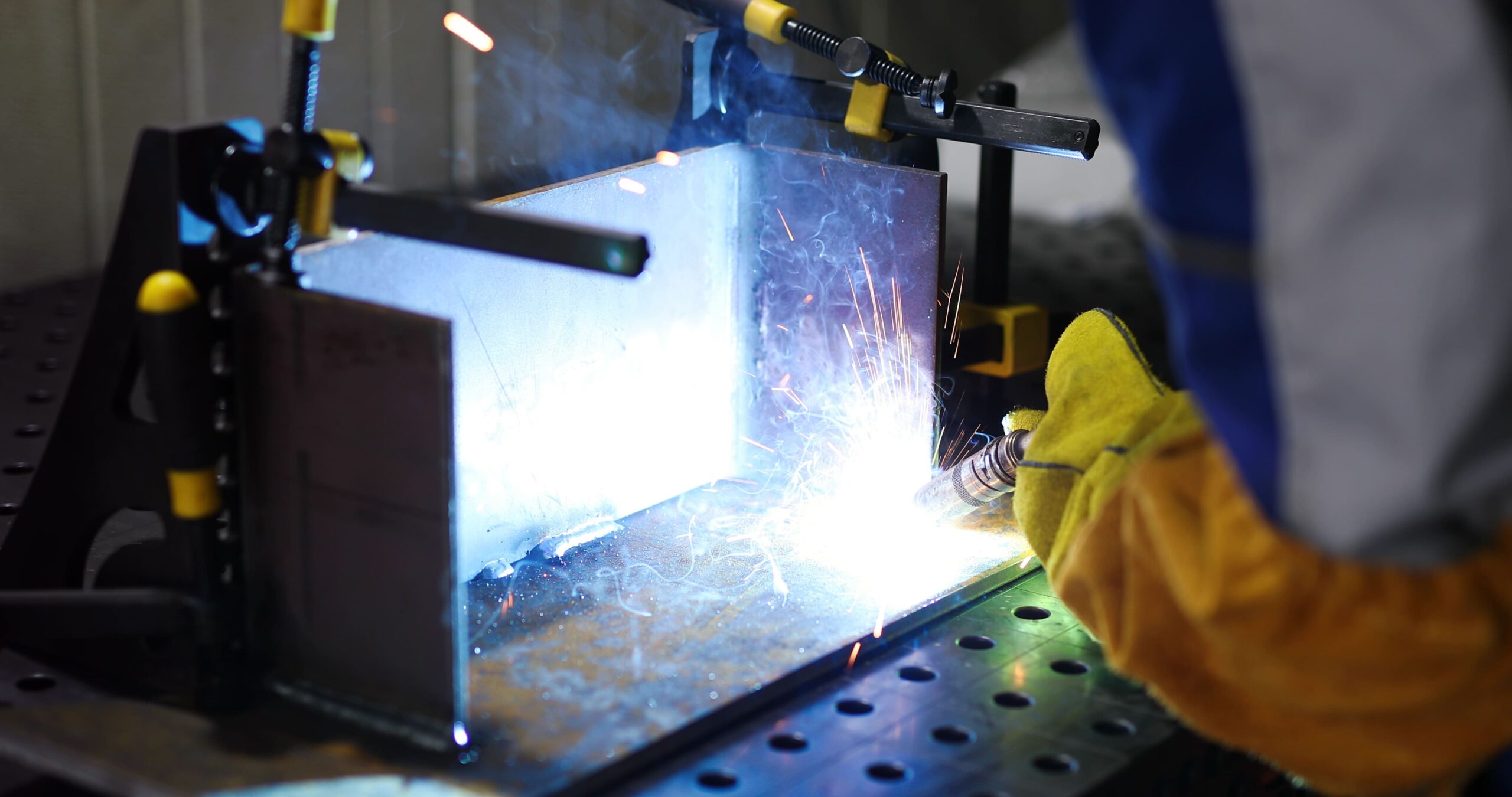
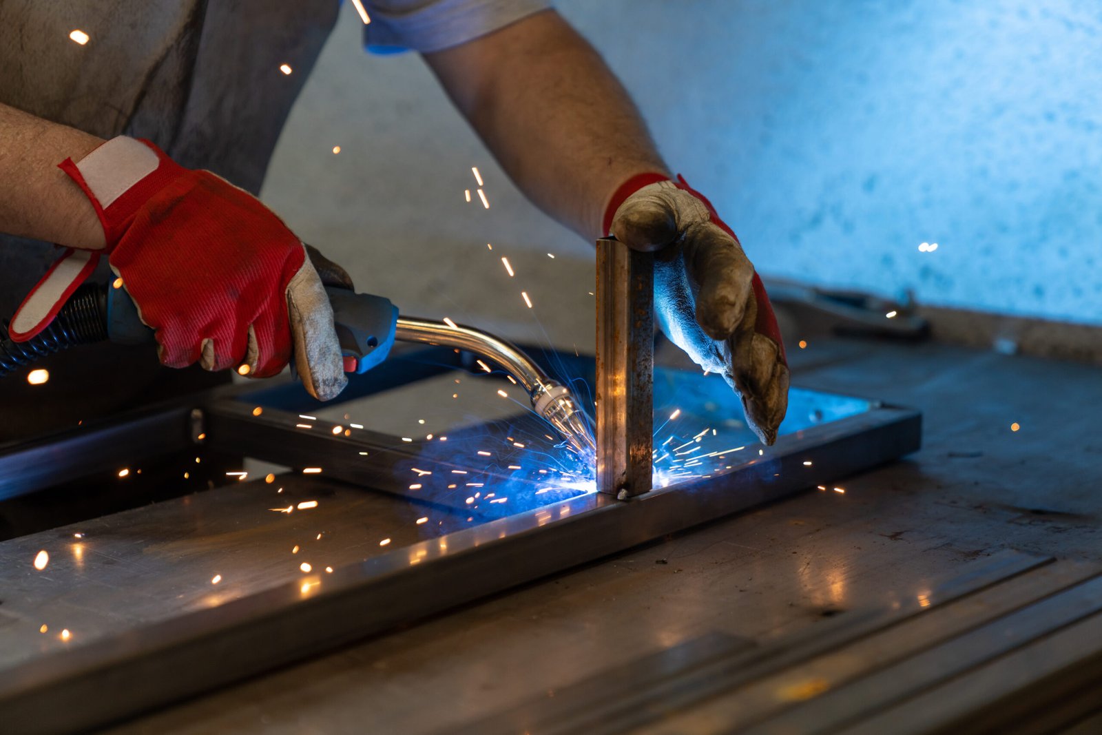
TENGHUI provides sheet metal welding services for custom brackets, panels, frames, chassis, enclosures, cabinets, and other fabricated assemblies. Available processes include laser welding, TIG welding, MIG welding, and resistance spot welding.

The welding method is selected according to your material, thickness, joint design, strength requirements, production quantity, and desired appearance. Controlled fit-up, suitable fixtures, and planned welding sequences help reduce thermal distortion and maintain important assembly dimensions.

Laser / TIG / MIG
Multi-Process Welding
Custom Fixtures
Low Distortion Control
Fast Turnaround
Prototypes & Serial Runs

Send your 2D drawings and 3D CAD files for a welding joint feasibility review and quotation.
All Design Uploads Are Secure & Confidential
Custom Sheet Metal Welding Services
Precision Fixture & Welding Setup

Sheet Metal Welding Capabilities

01
Laser Welding Precise & Low Distortion

Laser welding creates narrow, consistent weld seams with concentrated heat input. It is suitable for thin sheet metal, long seams, visible joints, and repeat production where reduced distortion and clean appearance are important.

02
TIG Welding High-Cosmetic Welds

TIG welding provides precise control over heat input and filler material. It is commonly used for stainless steel, aluminum, thin sheets, prototypes, complex joints, and cosmetic welds.

03
MIG Welding Structural & Assemblies

MIG welding provides faster welding speeds and efficient filler-metal deposition. It is suitable for carbon steel, stainless steel, aluminum frames, brackets, structural parts, and larger assemblies.

04
Resistance Spot Welding Fast & Consistent Joints

Spot welding joins overlapping sheet metal parts quickly and consistently. Typical applications include panels, cabinets, chassis, covers, brackets, and repeat production assemblies.

Joint Feasibility & Alloy Compatibility

Materials for Sheet Metal Welding

From structural steel frames to delicate cosmetic stainless and aluminum assemblies, we select suitable welding methods and fixtures to achieve high joint strength and minimal thermal distortion.
Welding Feasibility
Material & Method Match
Not every material grade or thickness is suitable for every welding process. For example, thin aluminum requires precise AC TIG or fiber laser welding, while galvanized steel demands special anti-porosity measures. Final feasibility and joint optimization are confirmed after engineering review of your 2D drawings and specifications.
Carbon Steel Sheet Metal Welding

Carbon Steel

MIG / TIG / Spot
Available Grades:

SPCC, SPHC, DC01, DC05, Q235, Q355

Welding Considerations:

Commonly used for brackets, frames, panels, and structural chassis. Offers excellent weldability across all standard fusion processes with high joint strength.
Stainless Steel Sheet Metal Welding

Stainless Steel

TIG / Laser
Available Grades:

SUS301, SUS304, SUS316, 316L

Welding Considerations:

Requires controlled heat input and inert gas shielding to limit thermal distortion, prevent burn-through, and avoid heat tint discoloration on cosmetic exterior seams.
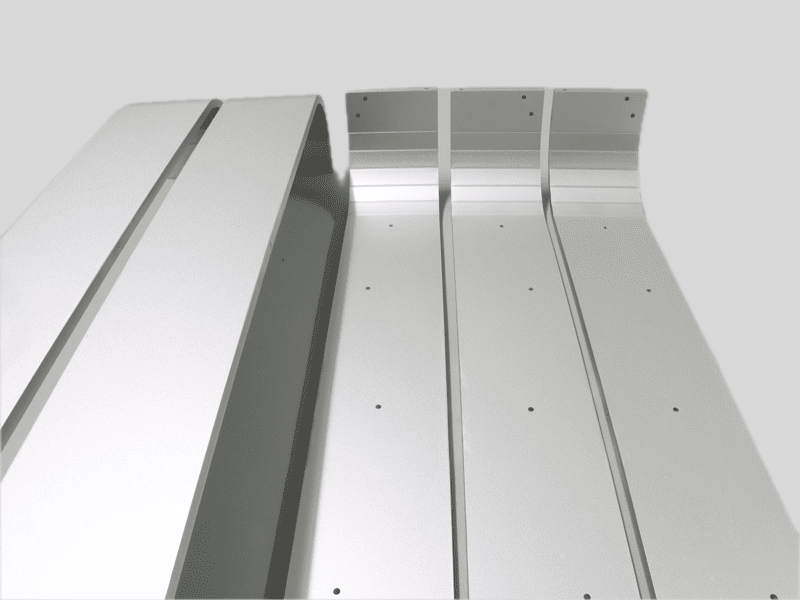
Aluminum Sheet Metal Welding

Aluminum

AC TIG / MIG
Available Grades:

5052, 5754, 5083, 6061

Welding Considerations:

Requires suitable filler wire (e.g., 4043 or 5356), thorough surface oxide cleaning, and pure argon shielding gas to prevent weld porosity and cracking.
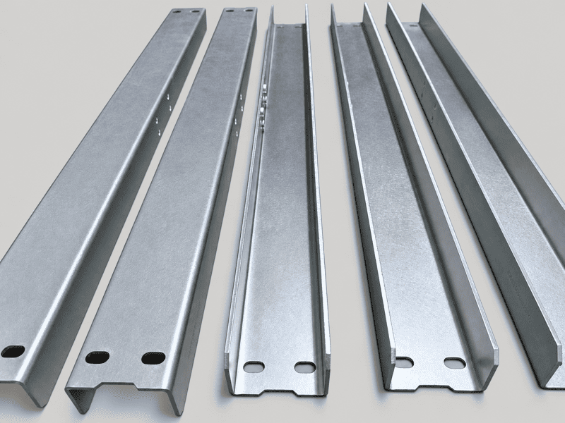
Galvanized Steel Sheet Metal Welding

Galvanized Steel

Spot / Brazing
Available Grades:

SECC (Electrolytic), SGCC (Hot-Dip)

Welding Considerations:

Requires engineering review because vaporized zinc affects weld pool stability and spatter. Resistance spot welding or zinc edge grinding is recommended for clean joints.
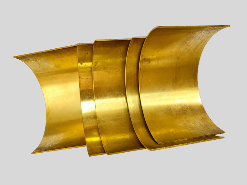
Copper and Brass Sheet Metal Welding

Copper & Brass

Laser / Brazing
Available Grades:

T2 Pure Copper, C110, H62, H65 Brass

Welding Considerations:

High thermal conductivity requires high energy density (such as fiber laser welding) or silver brazing. Joint feasibility is evaluated based on sheet thickness and application.

Welding Specification Advice: When joining dissimilar metals or specifying high-cosmetic stainless/aluminum welds, clearly designate exposed visible surfaces, weld bead flush-grinding requirements, and joint strength callouts on your 2D drawing.
Precision Fabricated Assemblies

Common Welded Sheet Metal Parts

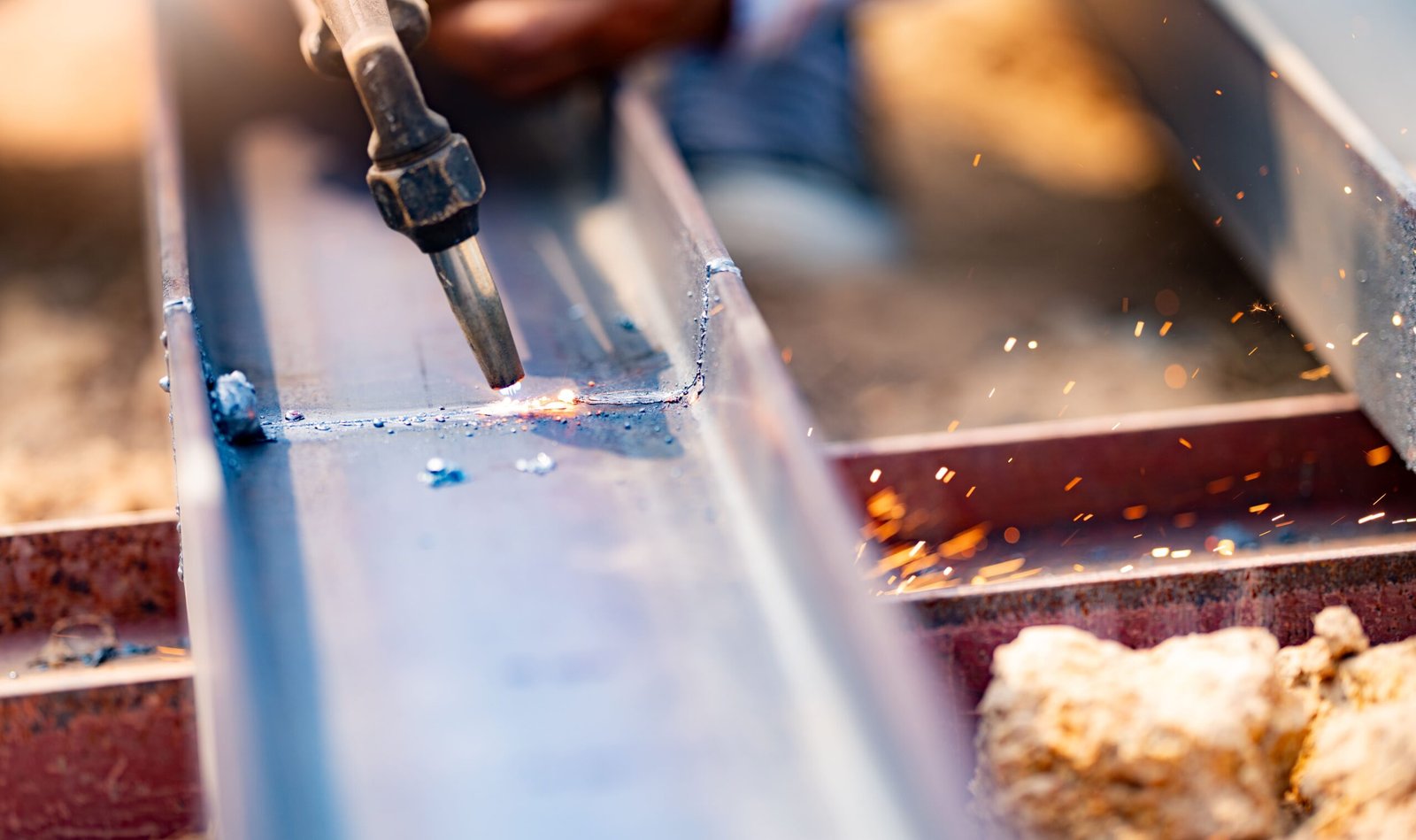
From heavy-duty structural machine frames to clean-finished cosmetic electronics housings, explore our custom welded assemblies engineered for strength and precision.
01

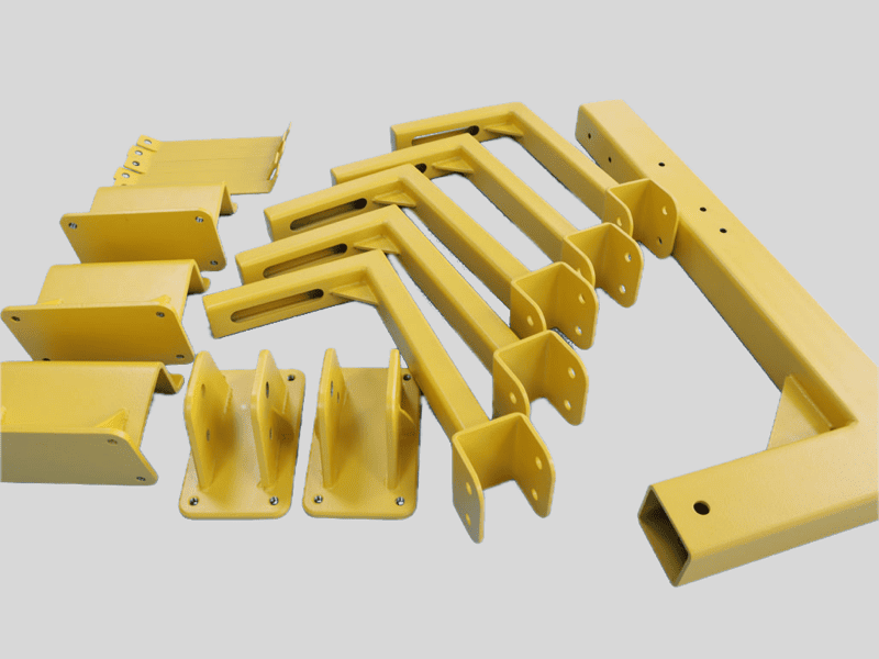
Brackets & Frames

Load-Bearing

Welded brackets, reinforcement braces, and heavy-duty structural frames designed to provide reliable load-bearing support, rigidity, and mechanical stability.

Heavy Load & Vibration Resistance
02

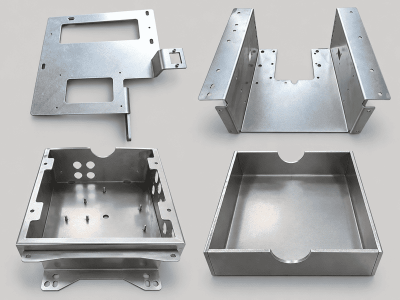
Electronic Chassis

Housings

Precision-welded electronic chassis and multi-side enclosure bodies built to house internal PCB components securely while maintaining tight interface tolerances.

Tight Interface Tolerances
03

Cabinets & Boxes

Enclosures

Robust electrical cabinets and automation control boxes featuring clean, sealed weld seams designed to protect sensitive internal electrical equipment.

Sealed Seams & IP Protection
04

Panels & Covers

Cosmetic

Custom equipment faceplates, exterior side panels, and protective covers fabricated with smooth, high-cosmetic weld finishes and corner blending for industrial devices.

Flush Corner Grinding
05

Guards & Trays

Safety & Racking

Safety machinery guards and reinforced mounting trays built to withstand rigorous industrial operational environments and secure moving automation components.

Reinforced Protective Envelopes
06

Stainless & Al Housings

Corrosion-Resistant

Specialized stainless steel and aluminum enclosures engineered for chemical corrosion resistance, cleanroom compliance, and lightweight structural performance.
Cleanroom & Anti-Corrosion
Custom Welding Solutions: Beyond these standard welded assemblies, we offer bespoke fixture design, post-weld joint grinding, and full DFM simulation tailored to your exact structural and cosmetic requirements.
Weld Integrity & Metrology Standards

Welding Quality and Distortion Control

Welding introduces localized heat, shrinkage, and residual stress. TENGHUI controls assembly precision and eliminates distortion through a structured 5-step engineering process.

Weld Quality
Distortion Control
Final assembly accuracy depends on material properties, joint preparation, thermal input, fixture stiffness, and sequenced welding paths. Our rigorous step-by-step verification ensures compliance with tight engineering drawing callouts.
STEP 01

Drawing & Joint Review

Material specifications, weld symbols, joint clearances, weld sizes, assembly tolerances, and cosmetic face requirements are systematically verified before production starts.

Joint DFM Feasibility
STEP 02

Fit-Up & Fixturing

Joint gaps, sheet alignment, torch access angles, and critical interface dimensions are validated on rigid modular clamping fixtures before any arc strikes occur.

Clamped Thermal Restraint
STEP 03

Controlled Parameters

Welding wattage, pulse current, travel speed, shielding gas flow rates, matched filler wires, and skip-welding sequences are calibrated to minimize heat-affected zones.

Minimized Heat Input
STEP 04

First-Article Check

The initial welded assembly is inspected for bead profile, dimensional stability, post-weld angular distortion, and assembly mating before batch replication begins.

FAI Dimension Sign-Off
STEP 05

Final Testing & QC

All accessible seams are visually checked for continuity, undercut, porosity, spatter, and burn-through. Critical flatness, squareness, and datums are verified per 2D prints.

100% CMM & Visual Audit
Additional Testing Services: Dye penetrant testing (PT), air-tight leak testing, pressure decay validation, or non-destructive testing (NDT) can be arranged upon request during the initial RFQ stage.
Assembly Accuracy & Tolerancing

Welded Assembly Tolerances

Welded assembly accuracy depends on the cumulative interaction of raw materials, joint configurations, clamping fixtures, and thermal management during fabrication.

Tolerance Factors
Structural Variance
A single generic standard tolerance cannot be applied to every welded assembly because localized welding heat and shrinkage affect different structures in different ways. Identify critical dimensions and inspection datums on 2D drawings so achievable limits can be confirmed prior to production.
01

Material & Thickness

Material Properties

Base material thermal expansion rates and sheet/plate thicknesses directly influence localized heat distribution and volumetric shrinkage during the welding cycle.

02

Assembly Size & Geometry

Structural Scale

Overall envelope dimensions, open-profile complexity, and asymmetrical spatial geometry dictate how cumulative residual stresses cause global thermal bowing or twist.

03

Weld Type, Length & Location

Seam Dynamics

Fillet vs. groove joint types, total deposited seam length, and spatial placement relative to the neutral axis determine the concentration and symmetry of shrinkage forces.

04

Continuous vs. Intermittent

Heat Input

Choosing between continuous hermetic seal welds and intermittent stitch/tack welding directly impacts overall heat input, cycle time, and total structural distortion.

05

Fixture Design & Datums

Alignment Control

Heavy-duty dedicated clamping fixtures and verified locating pins physically restrain dynamic movement and preserve tight relative component alignment while cooling.

06

Flatness & Squareness

Geometric Specs

Strict GD&T callouts for surface flatness, flange parallelism, and 90° squareness require balanced alternating weld passes and post-weld straightening operations.

07

Post-Weld Grinding & Finishing

Surface Finishing

Post-weld abrasive grinding, flush seam blending, or grain restoration can subtly alter local wall thickness and interface planes, which must be factored into finished tolerance planning.

Drawing Specification Note: Clearly identify critical assembly dimensions, datum planes, and inspection requirements on your 2D engineering drawing so achievable tolerances can be accurately verified during quotation.
Engineering Documentation Checklist

Drawing Requirements for Sheet Metal Welding

Clear, standardized 2D drawings paired with 3D CAD models prevent fit-up ambiguity, accelerate engineering DFM review, and ensure precise welding execution.

PHASE 01 SPEC

Joint & Seam Definition

Accurate base metal callouts and joint geometric parameters allow our welding engineers to select the exact torch setup, filler metal, and thermal sequence.

Essential for Weld Quoting
01

Material Grade & Thickness

Base Material

Specify the precise base alloy grade (e.g., SUS304, Al 5052-H32, SPCC) and exact sheet or plate thickness required for all welded assembly details.

02

Weld Type, Size, Length & Location

Seam Geometry

Clearly indicate the specific welding method, leg/throat seam dimensions, total weld length, and exact spatial placement along all joint interfaces.

03

Continuous vs. Intermittent Welding

Weld Pattern

Define whether the joints require continuous full-seam liquid-tight sealing or structured intermittent stitch welding with pitch and length callouts.

CAD Package Submission: Uploading complete 3D STEP/STP models alongside fully annotated 2D drawings accelerates our engineering DFM review, fixture feasibility evaluation, and quotation turnaround.

FAQ About Sheet Metal Welding

1. What welding processes does TENGHUI provide?

TENGHUI offers a comprehensive suite of metal fusion and joining solutions, including:

  • Fiber Laser Welding (Low heat input & minimal distortion)
  • TIG Welding (GTAW) (High-precision manual and semi-automatic welding)
  • MIG / MAG Welding (GMAW) (High-deposition structural fabrication)
  • Resistance Spot Welding (Fast, clean joining for thin-sheet overlapping flanges)
2. Which welding process is suitable for my parts?

The optimal welding process depends on part geometry, strength criteria, and cosmetic goals:

  • Laser Welding: Best for narrow, cosmetically critical joints and minimizing heat-affected zones.
  • TIG Welding: Provides pinpoint thermal control, high joint integrity, and clean bead aesthetics on stainless and aluminum.
  • MIG Welding: Highly efficient and cost-effective for heavy-duty structural frames, brackets, and longer continuous seams.
  • Resistance Spot Welding: Ideal for rapid, repeatable lap joints on sheet metal cabinets, covers, and enclosures without filler wire.

Our engineering team confirms the final process recommendation during pre-production DFM review.

3. Which materials can TENGHUI weld?

We routinely weld carbon steels (SPCC, SPHC, Q235, Q355), stainless steels (SUS301, SUS304, SUS316/316L), and aluminum alloys (5052, 5754, 5083, 6061). Specialized projects involving galvanized steel (SECC/SGCC), copper, brass, or titanium are reviewed individually to evaluate joint feasibility, shielding gas requirements, and zinc-coating mitigation.

4. How is welding distortion minimized?

We mitigate localized thermal expansion and residual stress through structured engineering controls: rigid modular clamping fixtures, precision laser-cut fit-up tolerances, staggered tack-welding, symmetrical skip-welding sequences, and precise heat-input management (pulse current / fiber laser parameters).

5. Can welded seams be ground smooth?

Yes. Mechanical flush grinding, corner seam dressing, and cosmetic surface blending (brushed or grain restoration) are standard post-weld options. Please clearly indicate Class-A visible exterior surfaces and required seam blending callouts on your 2D drawings so we can plan grinding allowances and surface finishing operations accordingly.

6. What files are required for quotation?

To receive a detailed quote and welding DFM assessment within 24 hours, please provide:

  • 3D CAD model in STEP or STP format (showing assembled configuration)
  • 2D technical drawing in PDF, DXF, or DWG with complete dimensions
  • Weld callouts & symbols (joint types, seam lengths, continuous vs. stitch)
  • Material grade, sheet thickness, inspection datums, and geometric tolerances
  • Total quantity and any cosmetic grinding or leak-testing specifications

Send us a message

If you have any questions or would like to book a session please contact us.

Send Us a Message

Once we receive your design files, our senior manufacturing engineers will manually perform a comprehensive DFM review and deliver an accurate, optimized quote within 24 hours.