TENGHUI provides large part CNC machining services for oversized plates, frames, baseplates, panels, tooling, and structural components made from metal and engineering plastics.
Our large-format CNC milling capabilities include machining ranges up to 3,000 × 2,000 × 100 mm for wide components or 4,500 × 600 × 100 mm for long parts. We support custom prototypes, low-volume orders, and repeat production with engineering review, machining, inspection, surface finishing, and worldwide delivery.
Upload your 3D CAD files and 2D drawings for a project-specific capacity, tolerance, and lead-time review
✅ All Design Uploads Are Secure & Confidential
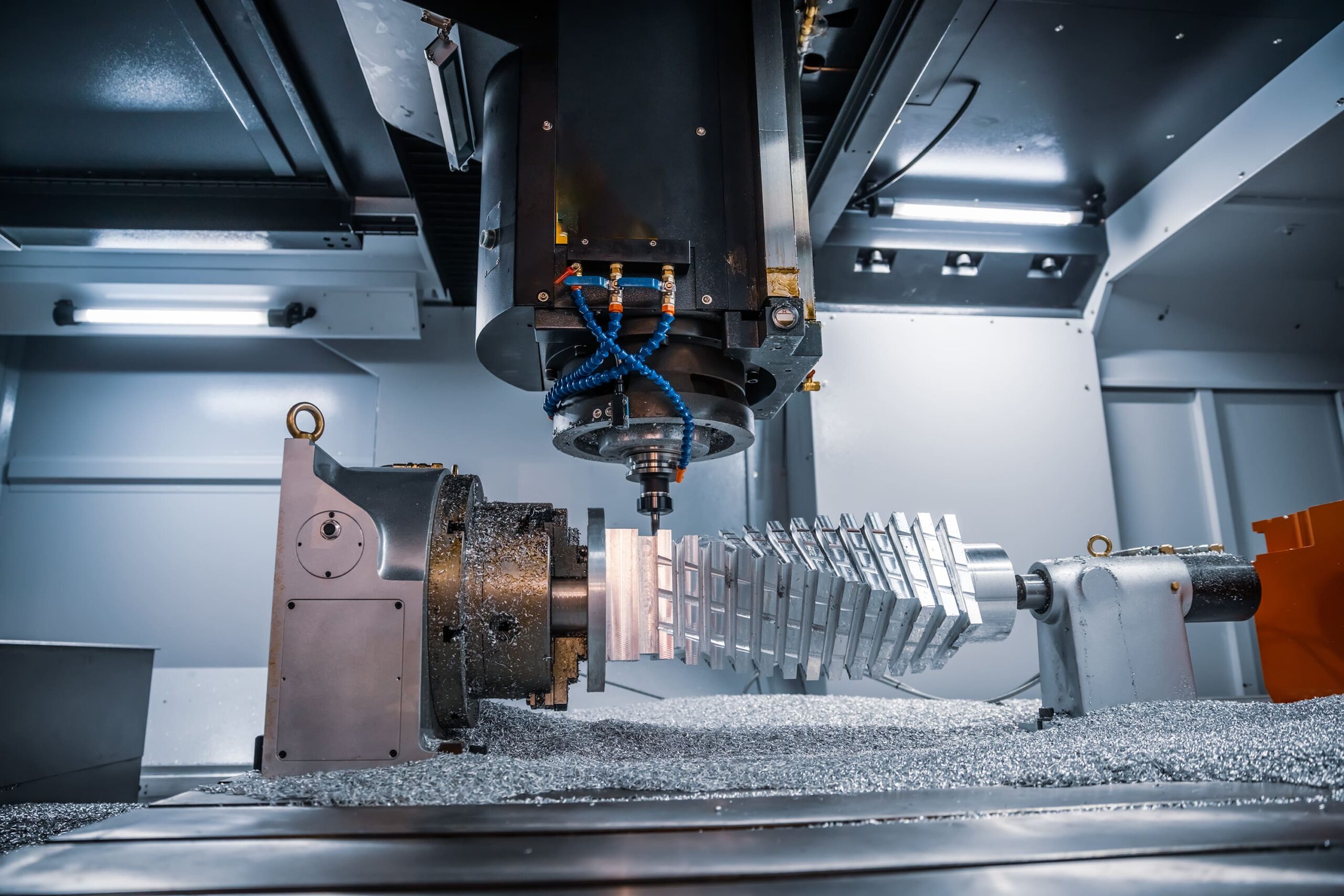
Large CNC parts require rigorous control of material internal stress, rigid workholding, thermal expansion, tool reach, and dimensional inspection. TENGHUI develops tailored machining strategies based on part geometry, material grade, tolerances, and batch volume.
Custom holes, pockets, slots, edge profiles, and mounting surfaces machined strictly to your drawings.
Optimized clamping setups and stress-relief strategies prevent deflection on extended linear features.
Machining Capability | Maximum Machining Range | Typical Components |
Wide-format CNC milling | 3,000 × 2,000 × 100 mm | Large plates, panels, tooling plates, baseplates and fixtures |
Long-part CNC machining | 4,500 × 600 × 100 mm | Rails, beams, profiles, long mounting plates and structural parts |
General machining tolerance | Typically ±0.05 mm | Subject to part size, geometry, material and feature location |
Selected critical features | Down to ±0.01 mm after review | Local precision features rather than the entire oversized component |
Production quantities | Prototypes to repeat production | Confirmed according to component size and machining time |
These are two separate machining ranges and should not be interpreted as a single 4,500 × 2,000 × 100 mm capacity.
Maximum workpiece size is also affected by clamping space, machining orientation, tool access, fixture design, and workpiece weight. Final capacity is confirmed after reviewing the complete drawings.
Our large-part CNC machining services support custom manufacturing of oversized structural, mounting, and guiding components across industrial equipment and automation systems.
We machine large, oversized components from a comprehensive selection of standard metals, alloys, and high-performance engineering plastics.
Large plates, weldments, and heavily machined parts contain residual stress. Heavy cutting redistributes this internal stress, leading to potential warping.
Oversized workpieces require rigid multi-point support. Excessive or uneven clamping force distorts the component during milling and causes spring-back error after release.
Long machining cycles and ambient temperature swings affect large dimensions—especially critical across long-span flatness, straightness, and parallelism.
Oversized components often exceed standard single-setup envelopes, requiring part flipping or repositioning along extended linear axes.
Provide clear, accessible datum surfaces for machining setups and CMM inspection. Avoid referencing features that become unreachable after the primary setup.
Oversized thin walls tend to chatter and warp during cutting. Maintain adequate structural wall thickness and avoid removing excessive material from only one side.
Generous internal corner radii allow the use of larger, more rigid end mills, reducing machining cycle times, tool deflection, and surface vibration.
Deep cavities require long-reach cutters and conservative feeds. Reduce pocket depth, enhance tool access, or increase corner radii wherever possible.
Apply tight limits only to features critical for mating, alignment, or function. Overly tight tolerances across an entire large component heavily inflate manufacturing costs.
When flatness, parallelism, perpendicularity, or true position are critical, define these GD&T symbols explicitly and separately on the 2D engineering drawing.
Oversized parts require reinforced crating and special freight logistics. Consider modular segmented designs to lower shipping costs when dividing does not compromise precision or function.
Inspection methods are carefully selected based on component dimensions, feature accessibility, geometric tolerance requirements, and available measuring envelopes.
Our available large CNC milling ranges include up to 3,000 × 2,000 × 100 mm for wide components or 4,500 × 600 × 100 mm for long components.
These are separate machining ranges. Final capacity depends on the part geometry, material, machining orientation, fixture space, tool access, and required features.
Our confirmed long-part machining range is up to 4,500 mm. For longer components, we can evaluate whether sectional machining, controlled repositioning, or a modular design is practical.
Feasibility must be confirmed after reviewing the drawings.
Our general machining tolerance is typically ±0.05 mm. Tolerances down to ±0.01 mm may be possible for selected local features after engineering review.
Overall flatness, parallelism, and positional accuracy across a large component must be evaluated separately.
Yes. We machine large aluminum plates with custom holes, pockets, slots, profiles, and mounting surfaces. Common materials include aluminum 6061, 5052, 5083, and 7075.
Plate size, thickness, flatness, temper, residual stress, and surface finish must be reviewed before production.
Yes, subject to engineering review. Feasibility depends on the material grade, dimensions, geometry, machining time, workholding, and tolerance requirements.
Steel and stainless steel generally require different tooling and machining parameters from aluminum.
Large weldments can be evaluated individually. Important considerations include welding distortion, residual stress, machining allowance, datum surfaces, and whether stress-relief treatment is required.
Please provide the assembly drawing, material specifications, overall dimensions, and critical machining requirements.
Inspection methods depend on the component size and tolerances. We may use micrometers, height gauges, indicators, straightedges, custom gauges, optical equipment, or CMM inspection where the component fits the available measuring range.
The proposed inspection method is confirmed during engineering review.
Please provide:
This information allows us to evaluate machine capacity, workholding, tolerance capability, production cost, packaging, and lead time.
Once we receive your design files, our senior manufacturing engineers will manually perform a comprehensive DFM review and deliver an accurate, optimized quote within 24 hours.