Skip to content
In-house CNC milling and turning for brackets, gripper components, housings, mounting plates, shafts, and fixtures.
TENGHUI supports prototypes and low-to-medium volume orders, with drawing review, coordinated finishing, and inspection of critical features.
We manufacture custom components for automation equipment builders, robotics developers, and system integrators. Our team reviews machining, assembly, and finishing requirements before production.
Production and inspection are managed against approved drawings and order requirements.
CNC milling and turning for metal and engineering plastic parts, from individual prototypes to repeat orders.
We review locating features, bearing fits, mounting holes, threads, and mating surfaces. Manufacturing concerns are raised before production.
Material grade, condition, and availability are confirmed during quotation. Required documentation and substitutions are agreed in advance.
Anodizing, plating, black oxide, and powder coating are evaluated for the material, contact conditions, and assembly requirements.
Straightforward CNC prototypes can often be completed in 3–7 working days. Quantity, complexity, finishing, and inspection determine the confirmed schedule.
TENGHUI manufactures parts for robotic assemblies, automated handling equipment, inspection systems, and production tooling.
We support fit checks, assembly trials, development builds, and repeat production. Each order follows the approved drawing revision and agreed acceptance requirements.

Typical projects include gripper fingers, motor adapters, sensor brackets, machined housings, fixture plates, and turned components.
Key requirements we review include:
In-house CNC machining, supported by sheet metal fabrication, rapid prototyping, and coordinated surface finishing.

Milled and turned components with defined mounting, locating, and mating features. Machining and inspection are planned around the drawing requirements.
Explore CNC Machining
Cut, bent, and assembled covers, panels, brackets, and enclosures. Welds, hardware, cosmetic surfaces, and final dimensions are reviewed before production.
Explore Sheet Metal
Machined and 3D-printed parts for fit checks, clearance reviews, and assembly evaluation. Material and process are selected according to the intended test.
Request Prototyping Quote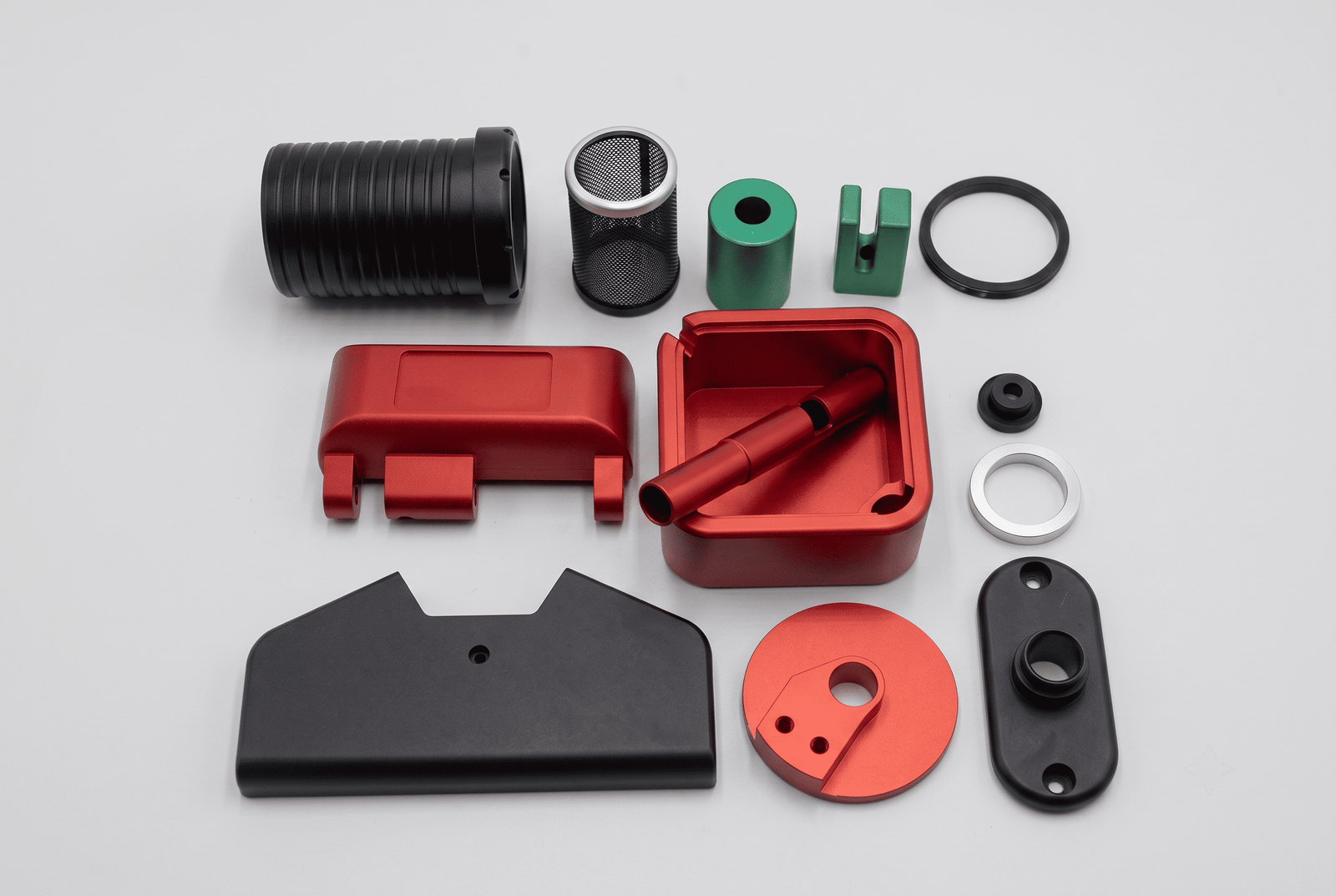
Finishes selected for appearance, corrosion exposure, wear, and contact conditions. Coating thickness and masking are considered at threads, fits, and electrical contacts.
Explore FinishingMaterial selection depends on loading, weight, contact conditions, temperature, and the operating environment.
| Material | Selection Notes | Typical Components |
|---|---|---|
| Aluminum 6061 | A common option for machined parts requiring low weight and finishing flexibility. | Mounting plates, brackets, gripper components, and housings. |
| Aluminum 7075 | Considered where higher strength is required; corrosion protection and assembly methods need review. | Loaded brackets, adapters, and tooling components. |
| Carbon & Alloy Steel | Grade and condition selected for strength, wear, welding, or heat treatment requirements. | Shafts, pins, fixture bases, and mounting blocks. |
| Stainless Steel 304 / 316L | Selected according to corrosion exposure and cleaning conditions. | Hardware, brackets, spacers, and equipment components. |
| POM / Acetal | Useful for selected sliding and locating applications; creep and temperature require consideration. | Bushings, guides, rollers, and spacers. |
| Nylon / PA6 / PA66 | Offers useful toughness and wear characteristics; moisture can affect dimensions. | Wear pads, rollers, guides, and protective components. |
| ABS | A practical option for machined covers and assembly models. | Enclosures, covers, and development parts. |
| PC / PMMA | Selected according to toughness, transparency, chemical exposure, and appearance requirements. | Viewing components, covers, and visual prototypes. |
Specify the material grade and condition on your drawing. Branded materials and alternative grades require confirmation before ordering.
Selected machined and fabricated parts demonstrating our capabilities in mounting, locating, handling, and equipment assembly.


Selected CNC-machined metal features can achieve tolerances as tight as ±0.01 mm, subject to engineering review.
Achievable limits depend on feature size, geometry, material, heat treatment, and finishing. Plastic parts require separate assessment of deformation, temperature, and moisture effects.
Specify fits and geometric tolerances individually. Dimensional reports and CMM inspection can be discussed during quotation.
We review locating surfaces, pin holes, bearing seats, mounting patterns, and their specified datum relationships.
Inspection focuses on the agreed features and measurement methods. Final alignment and motion performance also depend on the assembly design, mating components, and installation.
Include relevant mating details where they affect manufacturing or inspection.
Yes, subject to review of geometry, dimensions, material, and required features.
We assess tool access, workholding, machining sequence, and inspection access. Deep cavities, enclosed passages, and thin walls may require design changes or a different manufacturing route.
Manufacturing concerns are submitted for approval before production.
The finish depends on the base material, load, motion, mating surface, and environment.
Options such as hard anodizing, electroless nickel, or black oxide can be evaluated where appropriate. Wear resistance, friction, and corrosion protection are separate requirements and should be specified accordingly.
Identify treated areas, coating thickness, final dimensions, and any surfaces requiring masking.
Installation can be reviewed according to the drawing and assembly requirements.
Specify insert type, thread, installation depth, bushing fit, and any retention or inspection requirements. Adhesives, locking methods, and supplied hardware should be confirmed before production.
Each order is checked against the confirmed drawing revision, material, finishing, and inspection requirements.
Please identify changes to geometry, tolerances, or specifications when submitting a revised design. Changes affecting work in progress require review of cost and delivery.
Straightforward CNC prototypes can often be completed in 3–7 working days. Medium and larger production orders commonly require around 15–20 working days.
Material sourcing, quantity, complexity, finishing, and inspection may extend the schedule. Delivery is confirmed after technical review.
Please provide:
For moving assemblies, include relevant mating materials, clearances, contact conditions, and operating requirements.
Upload your 2D drawings (PDF/DWG/DXF) and 3D CAD files (STEP/IGES). We evaluate part geometry, materials, and tolerances within 24 hours.
Once we receive your design files, our senior manufacturing engineers will manually perform a comprehensive DFM review and deliver an accurate, optimized quote within 24 hours.