Skip to content
In-house CNC milling and turning for telescope components, optical mounts, housings, adapters, and retaining rings.
TENGHUI supports prototypes and repeat production, with coordinated surface finishing, inspection, and carbon fiber tube supply for suitable projects.
We manufacture mechanical components for telescopes, imaging equipment, and optical instrument assemblies. Our team reviews locating features, threads, mating surfaces, and finishing requirements before production.
Production and inspection are managed against approved drawings and order requirements.
CNC milling and turning for metal and engineering plastic components, from individual prototypes to repeat orders.
Experience supplying telescope-related aluminum parts and carbon fiber tubes, with dimensional, appearance, and packaging requirements reviewed for each order.
We review locating diameters, mounting faces, thread specifications, hole patterns, and access for machining and inspection.
Black anodizing, hard anodizing, painting, and other suitable treatments are reviewed for appearance, contact conditions, and finished dimensions.
Straightforward CNC prototypes can often be completed in 3–7 working days. Production, finishing, and carbon fiber tube schedules are confirmed separately.
TENGHUI manufactures mechanical parts that hold, connect, and support optical assemblies.
We support fit checks, assembly trials, development builds, and repeat production. Machining follows the agreed drawings; optical alignment and system performance remain subject to the assembly design and validation.

Typical projects include telescope mounting parts, machined housings, threaded adapters, flanges, rings, and sensor brackets.
Key requirements we review include:
In-house CNC machining, supported by sheet metal fabrication, prototyping, surface finishing, and carbon fiber tube supply.

Milled and turned housings, rings, adapters, and mounting parts. Critical features are reviewed for workholding, tool access, and inspection.
Explore CNC Machining
Cut, bent, and assembled covers, panels, brackets, and enclosures. Welds, hardware, light-blocking joints, and final dimensions are reviewed against the drawing.
Explore Sheet Metal
Machined and 3D-printed prototypes support fit checks. Carbon fiber tubes can be reviewed for specified diameters, finish, and mating interfaces.
Discuss Your Project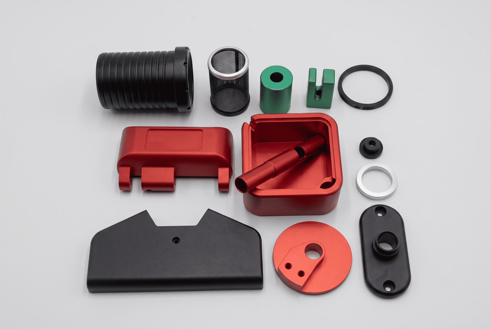
Black anodizing, painting, and other suitable finishes are coordinated. Specify cosmetic areas, coating thickness, masking, and adhesion requirements.
Explore FinishingMaterial selection depends on weight, stiffness, temperature, contact conditions, and finishing requirements.
| Material | Selection Notes | Typical Components |
|---|---|---|
| Aluminum 6061 | A common choice for lightweight machined parts and anodized finishes. | Housings, barrels, rings, adapters, and mounting plates. |
| Aluminum 7075 | Considered where higher strength is required; corrosion protection and assembly methods need review. | Loaded brackets, supports, and fixtures. |
| Brass | Suitable grades support detailed turning and threaded features; material and contact conditions require confirmation. | Adjustment components, spacers, and threaded rings. |
| Stainless Steel 304 / 316L | Selected according to corrosion exposure, loading, and surface requirements. | Hardware, shafts, spacers, and support components. |
| POM / Acetal | Useful for selected guides, spacers, and low-friction components; creep and temperature require consideration. | Bushings, guides, and locating parts. |
| PC / PMMA | Selected according to toughness, transparency, and chemical exposure. | Viewing covers and visual prototypes. |
| Carbon Fiber Composite | Tube construction, dimensions, finish, and connection details are project-specific. | Telescope tubes and tubular structures. |
Material grade, supply condition, availability, and documentation are confirmed during quotation. Transparent plastic parts are not supplied as precision optical elements unless separately specified and accepted.
Explore our portfolio of precision-machined prototypes and high-durability components manufactured for global optical equipment innovators.


Our focus is mechanical components for optical equipment, including housings, mounts, rings, adapters, brackets, and telescope-related parts.
We also review transparent plastic covers and prototypes. These should not be assumed to meet lens, mirror, imaging, or other precision optical specifications.
Selected CNC-machined metal features can achieve tolerances as tight as ±0.01 mm, subject to engineering review.
Fits and geometric requirements are assessed by feature, material, geometry, and finishing process. Specify datum references, thread requirements, surface roughness, and critical assembly relationships on the drawing.
Inspection methods and dimensional reports are agreed during quotation.
We review thread specifications, locating diameters, seating faces, and coating allowances before machining.
Identify any mating parts, gauges, or assembly samples needed for verification. Where finishing affects a fit, the drawing should clearly state the required finished dimensions and masking areas.
Yes. Black anodizing and suitable painted finishes can be reviewed according to the material and application.
A black appearance does not by itself establish low reflectance across all wavelengths. If stray-light control is critical, provide the wavelength range, reflectance requirements, and acceptance method.
Color, texture, adhesion, and areas requiring protection should be defined before processing.
Yes. We supply carbon fiber tubes for telescope projects and review inner diameter, outer diameter, length, finish, and mating requirements.
Specify painted and unpainted areas, interface dimensions, and inspection criteria. Tooling, sample approval, production quantity, and packaging are confirmed for each project.
Inspection follows the agreed drawing and order requirements. Dimensional reports and CMM inspection can be discussed for suitable features.
Cosmetic surfaces, threads, and mating areas are protected during handling and packing. Cleaning, particle limits, vacuum compatibility, or specialized packaging require separate review.
Straightforward CNC prototypes can often be completed in 3–7 working days. Medium and larger production orders commonly require around 15–20 working days.
Complex geometry, material sourcing, finishing, and inspection can extend the schedule. Carbon fiber tubes, new tooling, and sample approvals follow a separately confirmed plan.
Please provide:
For carbon fiber tubes, include diameter and length tolerances, construction requirements where specified, and the required finish on each surface.
Upload your 2D drawings (PDF/DWG/DXF) and 3D CAD files (STEP/IGES). We evaluate part geometry, materials, and tolerances within 24 hours.
Once we receive your design files, our senior manufacturing engineers will manually perform a comprehensive DFM review and deliver an accurate, optimized quote within 24 hours.